Suction from a falling material stream: design, dimensioning and practice

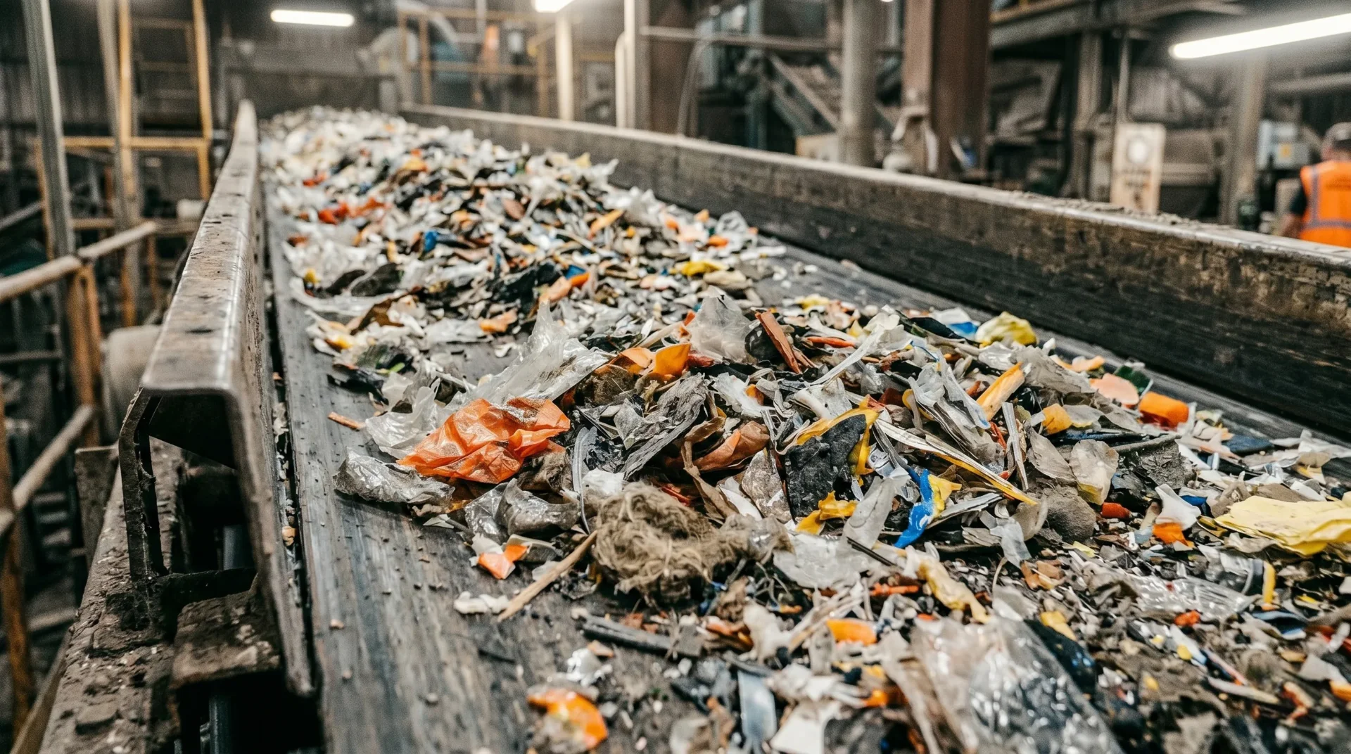
Suction from a falling material stream selectively separates light, recoverable components from heavy contaminants by inserting a suction probe directly into the drop chute to pneumatically capture the airborne fraction. This method is used at transfer points in cement plants, recycling facilities, lime plants and bulk material operations.
In vertical drop sections, particles reach velocities between 3 and 12 m/s depending on density and particle size. Suction exploits this density difference to achieve reliable separation and clean process air in the working area without moving parts in the material stream.
Why does particularly heavy dust arise at drop sections?
Falling bulk material displaces large quantities of air upward when entering a shaft or bunker, carrying fine particles along and emitting them as a dust plume from every open point. This effect intensifies with increasing drop height, material velocity and fines content.
Three physical mechanisms act together during the free fall of bulk material:
- Air displacement: the falling material takes up volume in the shaft and forces the existing air upward. The faster the material falls and the narrower the shaft cross-section, the stronger the displacement effect. In a shaft with 1,200 × 1,200 mm cross-section and a material flow of 50 t/h, air velocities of several metres per second develop.
- Entrained boundary layer air: every falling particle drags a thin layer of air along with it. At high particle concentrations, these boundary layers add up to a perceptible air flow that detaches fine dust from the material and carries it upward.
- Impact effect: when material strikes the bunker surface, a chute or a conveyor belt, agglomerates shatter. Fine particles are released and carried into the surroundings by the rising displacement air.
The combination of these three effects makes drop sections the most dust-intensive points in any bulk material plant. Conventional enclosures reduce dust emission but do not eliminate the cause. Targeted suction directly in the drop chute captures the dust-laden air where it forms and can simultaneously separate a material fraction selectively.
How does suction from a falling material stream work?
A suction probe extends at a defined angle into the drop chute and generates, via negative pressure, a directed air flow that draws light particles from the falling material while heavy components pass through unimpeded due to their higher falling velocity. The extracted material is separated from the conveying air via a cyclone.
The method is based on a straightforward principle: light particles have a high surface-to-mass ratio. Air resistance slows them more strongly than heavy, compact particles. When the suction velocity at the probe exceeds the settling velocity of the light fraction but remains below the settling velocity of the heavy fraction, selective separation occurs.
The configuration of such a suction system is divided into five functional sections:
- Suction probe in the drop chute: the probe is the central element. Position, angle and opening cross-section determine separation sharpness. Field trials show that a steep insertion angle into the falling material stream increases selectivity, because heavy particles with high vertical velocity pass the probe opening without being captured.
- Conveying duct: a pipe system transports the air-material mixture from the probe to the separator. The nominal diameter depends on the volume flow and material loading. Typical diameters range from DN 60 to DN 150 depending on throughput.
- Cyclone separator: the cyclone uses centrifugal force to separate the material from the air flow. The cleaned air leaves the cyclone upward, the separated material falls downward into a rotary valve. Volume flow and negative pressure must be matched to ensure the cyclone operates at its optimum working point.
- Vacuum generator: a side-channel compressor or radial fan delivers the required negative pressure. The choice of unit depends on the pressure drop of the total system. For applications in areas with explosive atmosphere, the fan must be ATEX-compliant.
- Secondary filter and discharge: a cartridge or bag filter cleans the residual air after the cyclone. Material discharge from the cyclone is dust-tight via a rotary valve or double flap into the downstream conveying system.
The entire system operates without moving parts in the material stream itself. Wear occurs only on the cyclone inner wall and at the bends in the conveying duct. This characteristic makes the method particularly low-maintenance compared with mechanical sampling devices or scrapers. The correct positioning of the suction probe in the drop chute is decisive for function.
What factors determine the position of the suction probe?
The separation performance of the suction depends primarily on the insertion angle, insertion depth and height position of the suction probe in the drop chute, because these three parameters define the interaction between suction velocity and particle falling velocity.
Insertion angle
The angle between the probe and the material stream is the most important individual parameter. Field trials at cement plants confirm: the steeper the probe extends into the falling material stream, the better the separation of light from heavy components. At a steep angle (60–80° to the horizontal), the suction flow meets the falling direction almost perpendicularly. Heavy particles pass the probe opening with high vertical velocity and are not captured. Light particles with low settling velocity follow the suction flow into the probe.
Insertion depth
The probe must extend far enough into the material stream to ensure representative capture, but must not block the material flow. For a shaft cross-section of 1,200 × 1,200 mm, the typical insertion depth is 200–400 mm. Too shallow a depth captures only the edge zone of the material stream, which is already dust-rich. Too great a depth creates material build-up above the probe.
Height position in the drop chute
The probe should be positioned in a zone where the material has already reached its full falling velocity but has not yet struck a chute or the bunker surface. In the acceleration zone directly below the feed point, separation is less selective because velocity differences between light and heavy particles are still small. At the optimum position, gravity has already translated density differences into measurable velocity differentials.
All three parameters must be matched to the specific installation situation. Shaft geometry, material properties and existing installations such as diverter chutes or impact plates influence the flow conditions in the drop chute. Probe design is the first step. Volume flow dimensioning follows as the second step.
How is the volume flow for the suction system dimensioned?
The required volume flow follows from the suction velocity at the probe opening, which must be higher than the settling velocity of the target fraction but lower than the settling velocity of the contaminants. Typical values for sampling suction systems are between 200 and 500 m³/h.
Four material parameters determine the dimensioning:
- Bulk density: light materials such as Fluff (100–200 kg/m³) require lower suction velocities than calciner fuel at 150–300 kg/m³. Bulk density determines how quickly the material accelerates in free fall.
- Particle size distribution: fine particles below 10 mm have a lower settling velocity than coarser pieces. The particle size of the target fraction defines the lower limit of suction velocity.
- 2D/3D ratio: flat, film-like 2D materials have a high drag coefficient. Compact 3D materials such as stones or metal parts fall almost unimpeded. The higher the 2D fraction, the easier pneumatic capture becomes.
- Moisture content: material with moisture contents above 15% by weight tends to clump and forms agglomerates with an elevated settling velocity. Volume flow must be set higher for moist material to keep the capture rate stable.
Alongside material parameters, the conveying path influences total requirements. Every pipe bend, height difference and metre of duct length generates pressure drop. The vacuum generator must compensate this pressure drop while maintaining the required volume flow at the probe. Dimensioning is carried out via a pressure drop calculation of the entire conveying path from probe to secondary filter.
In interval operation (typically 3 cycles per hour of 3–5 minutes each), the vacuum generator can be sized smaller than for continuous operation. The interaction between conveying pressure and air volume determines the optimum operating point of the system.
In which industries is suction from drop sections used?
Pneumatic suction from falling material streams is suitable for all industries where bulk materials are transported via drop chutes, chutes or transfer points, generating either dust emissions or requiring density-based material separation.
Six industries use the method:
- Cement industry: sampling and contaminant separation from alternative fuels at bunker transfer points. Calciner fuel, Fluff and Fesbo are sampled pneumatically at diverter chutes without heavy foreign objects blocking the pre-shredder.
- Recycling and waste management: separation of light film fractions from mineral impurities at transfer points of sorting plants. Suction supplements air classifiers and ballistic separators as the final separation stage.
- Mining and minerals: dust extraction at crusher outlets, screen transfers and bunker loading. Limestone, gypsum and ore dusts are captured directly at the drop point before they disperse in the hall.
- Potash and salt industry: extraction of hygroscopic fine dusts at transfer points of conveying systems. The captured air is cleaned and recirculated to minimise energy losses through exhaust air.
- Food industry: dust extraction at silo filling points and mill outlets during the processing of flour, sugar and starch. The explosion characteristics of these organic dusts require particular care in system design in accordance with EU ATEX requirements.
- Wood and biomass logistics: capture of fine dust during the transfer of wood chips, pellets and sawdust into silos and bunkers. The hazard classification of these dusts determines the required filter class of the suction system.
In each of these industries, pneumatic suction replaces or supplements conventional dedusting solutions such as enclosures with suction connections. The difference: suction from the material stream itself acts selectively and can, alongside dust capture, achieve targeted material separation. The design must take industry-specific requirements into account, particularly in the area of explosion protection.
What explosion protection requirements apply to the suction system?
Suction systems at drop sections must be designed for use in potentially explosive atmospheres in accordance with ATEX Directive 2014/34/EU, with the zone classification at the installation site specifying the permitted equipment category for each component. Not every transfer point requires ATEX equipment.
The Ex requirements depend on two factors: the dust type and the zone classification on site. At transfer points without dust extraction, no Ex requirements exist in many cement plants because dust concentration remains below the lower explosive limit. At dust extraction systems, Zone 21 typically applies on the raw gas side and Zone 22 on the clean gas side within approximately 1 m of the discharge opening.
If the installation site falls within an Ex zone, five components must be ATEX-compliant:
- Fan: spark-free design with equipment category corresponding to the zone. Category 3 is sufficient for Zone 22; Category 2 is required for Zone 21. Explosion-protected fans use impellers of aluminium or spark-free alloys.
- Pipework: conductive material with continuous earthing. Electrostatic charging in plastic pipes is a frequent ignition source during dust conveying.
- Cyclone: pressure relief area or pressure-shock resistance. For dusts with high explosion characteristics, a suppression system may additionally be required.
- Secondary filter: conductive filter media, earthing of all metal parts, pressure relief or pressure-shock-resistant design.
- Rotary valve: ATEX-certified design with torque monitoring as a flameback barrier between cyclone and conveying system.
The complete Ex requirements for the suction system must be documented in the workplace explosion protection document. Documentation covers zone assignment, equipment categories and inspection intervals for each component.
What operating modes are possible?
Suction from falling material streams can be configured as continuous operation for ongoing dedusting, as interval operation for cyclical sampling, or as demand-controlled operation with automatic activation on material flow. Each mode places different demands on the system technology.
Continuous operation
In continuous operation, the suction system runs throughout the entire production period. This mode is suitable for ongoing dedusting at transfer points with permanent material flow. Filter elements must be designed for long service lives. The cyclone requires wear-resistant inner surfaces, typically Hardox or ceramic linings. Energy consumption is constant but can be matched to actual demand using variable frequency fans.
Interval operation
Interval operation is the typical mode for sampling. The system extracts material in defined time windows, for example 3 cycles per hour of 3–5 minutes each. Between cycles the system is at standstill. This mode allows more compact systems with smaller fans and filters. Control is time-based or via a signal from the process control system.
Demand-controlled operation
Sensors at the drop chute detect when material is falling and activate the suction automatically. This mode combines low operating costs with complete capture. Inductive sensors, microwave barriers or flow meters provide the start signal. The suction continues with an adjustable run-on time to capture residual dust after the material has passed through.
The choice of operating mode determines the sizing of the vacuum generator, filter size and cyclone wear. In interval operation, energy consumption is a fraction of continuous operation, making pneumatic sampling economically attractive as well.
Suction systems for drop sections from Kiekens
Kiekens has been developing tailored suction systems for industry for over 100 years. For suction from falling material streams, Kiekens supplies complete solutions from a single source: suction probe, conveying duct, cyclone separator, vacuum generator, secondary filter and dust-tight discharge into the existing conveying system.
The design is based on specific material data, drop chute geometry and operational requirements. Whether sampling in interval operation or continuous dedusting at the transfer point, Kiekens supports projects from feasibility analysis through technical dimensioning to installation and commissioning. Contact Kiekens for individual advice.
Retrofitting is possible in most cases. The suction probe is inserted into the shaft wall via a flange or pipe penetration. Cyclone, fan and filter are installed beside the shaft. The required floor space is 2–6 m² depending on system size. The prerequisite is an accessible point on the shaft where the probe can extend into the material stream without obstructing the flow.
The cyclone inner surface lasts 12–24 months in continuous operation with Hardox lining for abrasive materials. In interval operation, service life extends accordingly. Filter cartridges are replaced every 3–6 months depending on dust load. The suction probe itself is subject to the greatest wear and should be manufactured from wear-resistant steel or fitted with a ceramic inner lining.
Both functions can be combined. In continuous operation, the entire extracted material stream is dedusted and returned to the conveying system. For sampling, a partial quantity is periodically diverted via a diverter valve into a separate sample container. Switching is automatic via the process control system.
Energy consumption depends on volume flow and operating mode. A typical sampling suction system with 300 m³/h requires a fan with 3–5.5 kW drive power. In interval operation with 15 minutes run time per hour, this results in consumption of 0.75–1.4 kWh per hour. Variable frequency drives additionally reduce consumption in part-load operation.


%20(1).jpg)