Separating contaminants from alternative fuels: methods, technology and suction solutions


What are contaminants in alternative fuels?
Contaminants are all material components in alternative fuels that impair the combustion process, material handling or sampling, and do not contribute to the desired calorific value. The type of contaminants varies depending on the input material and the degree of processing.
Alternative fuels are derived from commercial and industrial waste, sorting residues and production rejects. Processing includes shredding, screening, magnetic separation and air classification. Despite these process steps, foreign objects remain in the material stream and can be divided into two groups.
Five contaminant types occur most frequently in practice:
- Metallic contaminants: steel parts, wires, screws and aluminium residues from incomplete magnetic separation or eddy current sorting
- Mineral contaminants: glass shards, ceramic fragments, stones and concrete residues with material densities between 2,000 and 2,500 kg/m³
- Heavy organic contaminants: wet wood, rubber parts and textile bales with high moisture content above 30% by weight
- Oversized components: 3D materials above the specified particle size that block pre-shredders and dosing equipment
- Chemical contaminants: PVC-containing fractions with chlorine contents above 1%, causing corrosion in the kiln system
The effects of these contaminants range from mechanical blockages to emission problems. Heavy and dense foreign objects are particularly critical: they jam pre-shredders and interrupt the entire sampling and dosing sequence. Separating these contaminants requires methods that exploit physical properties such as density, size and aerodynamic behaviour.
Why do contaminants reach the material stream despite upstream processing?
Contaminants pass through upstream processing because no single separation method captures all types of foreign objects simultaneously, and the heterogeneity of the input material in alternative fuels is extremely high. Even multi-stage processing plants do not achieve one hundred percent separation.
Three causes explain the problem:
- Process limits of magnetic separation: overhead belt magnets and drum separators capture only ferromagnetic metals. Stainless steel, aluminium composites and metal-coated plastics pass through magnetic separation undetected. Eddy current separators separate non-ferrous metals but fail with particles smaller than 1–3 mm depending on configuration.
- Limits of screen classification: glass shards and ceramic fragments with particle sizes between 10 and 30 mm fall into the same screen fraction as the desired refuse-derived fuel fraction. Screening separates by size, not by material type.
- Varying input quality: commercial waste varies considerably in composition depending on supplier, region and season. Processing plants are designed for a certain average. Peaks in contaminant levels overwhelm the installed sorting technology.
The remaining contaminants concentrate primarily at transfer points and in drop chutes, where the material changes speed and direction. These are precisely the locations where pneumatic methods can separate light from heavy components.
What methods separate contaminants from alternative fuels?
Contaminant separation in alternative fuel processing uses four separation principles, each exploiting different physical properties of the materials: magnetism, density, aerodynamic behaviour and optical characteristics.
Magnetic separation and eddy current sorting
Overhead belt magnets extract ferromagnetic components from the material stream. Drum separators also capture weakly magnetic particles at lower conveying speeds. Eddy current separators generate an alternating field that induces eddy currents in electrically conductive non-ferrous metals such as aluminium and copper, propelling these particles out of the material stream. The combination of both methods removes the majority of metallic contaminants.
Air classification and ballistic separation
Air classifiers use a defined air flow to separate light, airborne components such as films and paper from heavy contaminants such as glass, stones and metals. Ballistic separators combine inclination, vibration and air flow. Flat 2D materials migrate upward over the screen surface, while heavy 3D materials roll downward. Air classification is the central method for density-based separation and forms the basis for pneumatic contaminant separation.
Sensor-based sorting
Near-infrared sensors (NIR) identify materials based on their reflection spectrum. PVC-containing fractions that are not detectable by mechanical methods can be selectively discharged using NIR technology. X-ray fluorescence (XRF) detects metallic impurities in mixed fractions. Both methods work inline and enable sorting at belt speeds of up to 5 m/s.
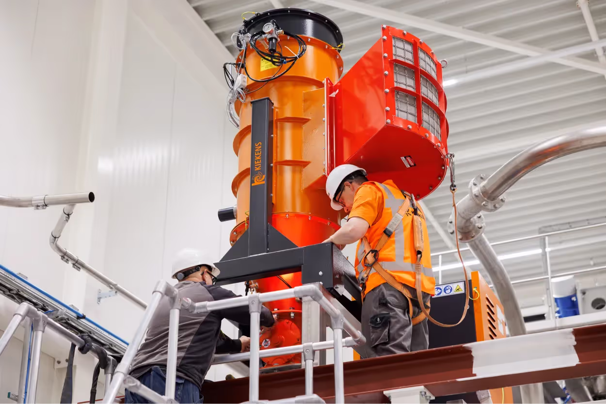
Pneumatic suction from the material stream
Pneumatic suction separates materials directly in the falling material stream according to their aerodynamic behaviour. A suction probe extends into the drop chute and captures the light, air-rich components, while heavy contaminants fall downward under gravity. The extracted material is separated from the conveying air via a cyclone separator and discharged into the downstream conveying system.
Pneumatic suction supplements upstream methods at a critical point: the transfer point in the plant itself. While magnetic separation and air classification take place in the processing plant, suction acts directly upstream of the dosing equipment or the pre-shredder.
How does pneumatic contaminant separation work at transfer points?
Pneumatic contaminant separation uses a directed air flow to selectively extract the light, fuel-relevant fraction from a falling material stream, leaving heavy contaminants behind in the drop chute. The method is based on the density difference between the desired fuel and unwanted foreign objects.
The configuration of a pneumatic suction system at a transfer point comprises four main components:
- Suction probe: the probe extends at a defined angle into the falling material stream. The steeper the angle, the more selective the separation between light and heavy components. The optimum angle depends on the drop height, material density and particle size distribution.
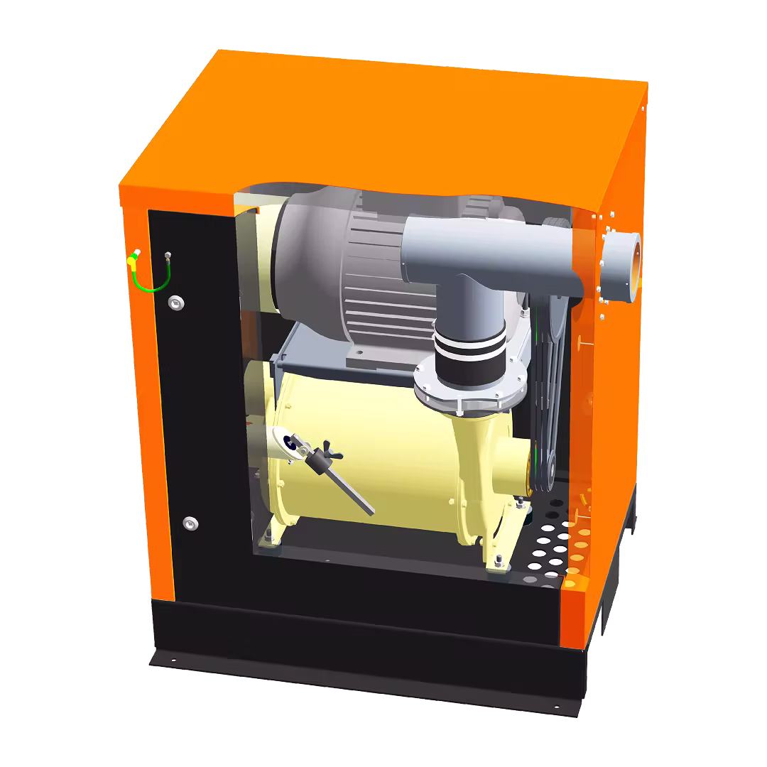
- Vacuum generator or fan: a side-channel compressor or radial fan generates the required negative pressure. Typical volume flows for sampling suction systems range from 200 to 500 m³/h at negative pressures of 50 to 150 mbar.
- Cyclone separator: the cyclone separates the extracted material from the conveying air by centrifugal force. The separated material falls via a rotary valve into the downstream conveyor screw.
- Secondary filter: a cartridge or bag filter cleans the residual air before it is returned to the hall or discharged to the outside. The secondary filter protects the fan from fine dust wear.
The decisive advantage over mechanical sampling devices: suction selectively captures the light fraction. Heavy contaminants such as steel parts, glass shards and stones do not reach the suction probe because their falling velocity exceeds the suction velocity. The material separated in the cyclone is largely free of contaminants and can be shredded, analysed or dosed directly.
Field trials at cement plants confirm this principle. Suction tests with suction nozzles of nominal sizes DN 60 to DN 80 show that separation sharpness increases with a greater insertion angle of the probe. The system design must be tailored to the specific material properties: bulk density, moisture content, particle size distribution and the ratio of 2D to 3D material.
What requirements do KBS, Fluff and Fesbo place on contaminant separation?
Calciner fuel (KBS), Fluff and Fesbo (solid secondary fuel) differ considerably in particle size, bulk density and susceptibility to contaminants, which is why the suction and separation parameters must be individually designed for each fuel type.
Calciner fuel (KBS)
KBS consists entirely of 2D material with particle sizes below 250 mm and contains up to 15% 3D material below 100 mm. Bulk density ranges from 150 to 300 kg/m³, moisture content below 20% by weight. Calciner fuel is fed into the kiln system via the calciner. Contaminants in this material stream enter the combustion process directly and can cause build-up, blockages and increased emissions. The higher density and greater 3D fraction compared to Fluff make KBS more susceptible to heavy contaminants such as metal parts and ceramic fragments.
Fluff
Fluff is the lightest fraction among alternative fuels. The material consists almost entirely of 2D components below 30 mm with bulk densities of 100 to 200 kg/m³ and moisture contents below 10% by weight. Fluff has the highest calorific value because the processing has already passed through several sorting stages and the material consists predominantly of film chips. The low 3D fraction below 10% makes Fluff particularly well suited for pneumatic separation, as the density difference between fuel and contaminants is at its maximum.
Fesbo (solid secondary fuel)
Fesbo refers to solid secondary fuels with defined quality parameters and European waste classification codes. Composition varies more than for Fluff or KBS, as different waste streams serve as input material. Fesbo requires close-meshed sampling to monitor calorific value, chlorine content and contaminant fraction. Pneumatic suction is particularly suitable for Fesbo sampling because it provides a representative, low-contaminant sample without mechanical sampling devices being blocked by foreign objects.
All three fuel types benefit from pneumatic contaminant separation at the transfer point in the cement plant. The design differs in volume flow, suction velocity and cyclone sizing. The suction system must be planned as a complete solution so that all components are matched to one another.
How is a contaminant separation suction system designed?
The design of a pneumatic suction system for contaminant separation is based on the material properties of the alternative fuel, the geometry of the transfer point, and the desired operating mode (continuous or interval operation). Six parameters determine the dimensioning:
- Bulk density of the material: light materials such as Fluff (100–200 kg/m³) require lower suction velocities than KBS (150–300 kg/m³). Bulk density determines the ratio of air volume flow to material conveyance.
- Particle size distribution and 2D/3D ratio: flat, airborne 2D materials are captured more easily than compact 3D particles. A high 2D fraction allows lower volume flows and smaller pipe cross-sections.
- Moisture content: material with more than 15% moisture tends to stick in the cyclone and conveying duct. Moist materials require larger pipe diameters and smooth inner surfaces.
- Drop chute geometry: shaft cross-section, drop height and position of the diverter chute determine where the suction probe is optimally positioned. The probe must extend far enough into the material stream without blocking the flow.
- Operating mode: continuous operation for ongoing contaminant separation requires longer service lives for filter elements and wear-resistant cyclone inner surfaces. Interval operation for sampling (typically 3 cycles per hour of 3–5 minutes each) allows more compact systems.
- Conveying path and discharge: duct length between suction probe and cyclone, height difference and number of bends determine pressure drop. Discharge from the cyclone must be dust-tight into the downstream conveyor screw or collection vessel.
The design requires experience with pneumatic conveying systems and specific knowledge of the behaviour of alternative fuels in an air stream. Standard solutions rarely work for these applications because every transfer point has different space conditions and material properties.
What advantages does pneumatic suction offer over mechanical methods?
Pneumatic suction separates contaminants selectively by density and aerodynamic behaviour, while mechanical sampling devices capture the entire material cross-section and include heavy foreign objects in the sample. This difference determines the availability of downstream plant components.
Six advantages support the pneumatic solution:
- Selective separation: heavy contaminants such as steel parts, glass shards and stones do not reach the suction probe because their falling velocity exceeds the suction velocity. Mechanical slide-plate sampling devices capture the entire cross-section including all contaminants.
- No blockages in the pre-shredder: since heavy and hard foreign objects do not enter the conveying system, the regular downtime caused by jammed pre-shredders is eliminated. Plant availability increases measurably.
- Low mechanical wear: the suction system has no moving parts in the material stream. Mechanical sampling devices such as slide plate or pivot pan systems wear through contact with abrasive contaminants.
- Interval and continuous operation possible: suction can be time-controlled for individual sampling (3–5 minutes per cycle) or as continuous operation for ongoing contaminant separation.
- Representative samples: the extracted fraction corresponds to the fuel-relevant portion of the material stream. Samples from pneumatic suction represent the actual quality of the alternative fuel at the burner more accurately than cross-sectional samples containing contaminants.
- Retrofittable at existing transfer points: suction probe, cyclone and fan can be installed at existing drop chutes and chutes without rebuilding the existing conveying technology.
Pneumatic suction does not replace upstream processing technology. Magnetic separation, air classification and NIR sorting remain necessary in the RDF processing plant. Suction supplements these methods as the final separation stage directly in the cement plant, where it counts: before the pre-shredder, before dosing, before the burner.
Contaminant separation suction systems from Kiekens
Kiekens has been designing and realising industrial suction systems for demanding applications for over 100 years. For contaminant separation from alternative fuels, Kiekens offers tailored complete solutions from a single source: suction probe, cyclone separator, fan, secondary filter and dust-tight discharge into the downstream conveying technology.
System design is based on specific material data, the geometry of the transfer point and the desired operating mode. Kiekens supports projects from feasibility analysis through technical dimensioning to installation and commissioning. Contact Kiekens for individual advice on your specific application.
Even at a contaminant level of 2–5% in the input material, the investment pays off when contaminants regularly cause downtime at the pre-shredder or dosing equipment. A single unplanned shutdown in a cement plant costs several thousand euros per hour, depending on kiln capacity.
Regular maintenance covers three items: filter replacement at the secondary filter (every 3–6 months depending on dust load), wear inspection of the cyclone inner surface (annually), and checking the seals at the material discharge. Moving parts are limited to the fan and the discharge lock.
Yes. The suction control can be connected via PLC to the plant’s process control system. Typical interfaces are Profinet or Modbus TCP. Set and actual volume flow, differential pressure at the filter and operating hours can be centrally monitored and used as triggers for maintenance notifications.
This depends on the zone classification at the installation site. At transfer points without dust extraction, ATEX requirements often do not apply. In dust extraction systems in cement plants, Zone 21 typically applies on the raw gas side and Zone 22 on the clean gas side. In these zones, the suction system must be ATEX-compliant, with spark-free fans, conductive ducts and an earthing concept.